
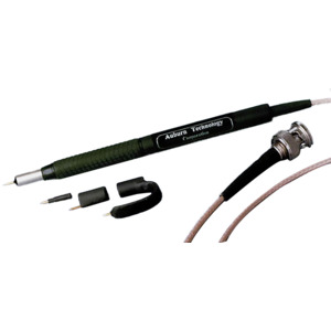
Auburn P-20A Passive RF Probe, 100 kHz to 3 GHz Bandwidth, 50 V
Our Part #10281874
Mfr Part #P-20A
Auburn P-20A Passive RF Probe, 100 kHz to 3 GHz Bandwidth, 50 V
Our Part #10281874
Condition:NEW
Mfr Part #P-20A
- Description
- Specifications
3GHz RF Probe BNC. (adaptor for SMA not included )
- Low Distortion, Passive RF Design
- Light RF Loading Characteristics
- Internal 50V DC Block
- 10:1 Voltage Ratio
- dBm Power Readings
- 20dB Attenuation: when Probing 50 ohm RF Circuits
- Bandwidth: 100 kHz to 3 GHz
- Rugged Design
- 1 GHz Long Ground Clip
- 2 GHz Short Ground Clip
- Center Pin Extender
- Cushioned Finger Grip
- P-20A Users Guide
The P-20A is a Passive 10:1 RF Voltage Probe with a 50 Volt DC Block built in. It has been designed to allow users of RF test equipment to use standard signal tracing techniques. The P-20A makes it possible to conveniently and accurately monitor or inject signals up to 3 GHz into RF circuits without significantly loading or detuning them. The P-20A comes with Interchangeable Ground Clips that adapt to a wide range of applications.
Theory of Operation
A frequency compensated 450 ohm resistive element is utilized in the probe’s design to reduce circuit loading and to give the P-20A a 10:1 VOLTAGE RATIO when connected to a 50 ohm instrument and probing a 50 ohm source. Special construction techniques of the P-20A produce less than 1 pf of stray capacitance at 1 Mhz to minimize the capacitive loading affects on RF circuits. RF instruments require low inductance grounding to make consistent and accurate measurements. TheP-20A’s Interchangeable Ground Clips provide low inductance grounding and the ability to make contact with the circuit’s active RF ground. To prevent false readings or damage to test equipment, an internal DC blocking capacitor ( 50 volts MAX. ) is provided to decouple in-circuit supply voltages.
RF Grounding
To obtain consistent and accurate RF amplitude measurements PROPER RF grounding is REQUIRED.
Measurements from 100 kHz to 1 GHz can be accurately measured by directly grounding the P-20A’s grounding barrel or by using the short pin or flexible ground clip. Frequencies from 1 to 2 GHz will require direct grounding of the P-20A’s grounding barrel or the use of the short pin ground clip. Frequencies from 2 to 3 GHz will require direct grounding of the P-20A’s grounding barrel. See Typical P-20A probe response for more information.
Ground clips can be changed by grasping the ring portion of the clip and twisting it, while pulling to remove or pushing to assemble. Moderate force may be required.
If a good RF ground is out of reach, a 6 inch metal ruler or similar item can often be used to extend the ground to the probe. To minimize inductance, it’s better to make direct contact with the grounding barrel of the probe.
Verification of a low inductance RF ground can be accomplished by slightly changing the P-20A ground contact position while observing that there are no significant changes in readings.
RF Voltage Measurements
RF Voltage Measurements from 100 kHz to 3 GHz can be made at 7 Volts RMS continuously or up to 35 Volts RMS for one second.
The P-20A produces a 10:1 VOLTAGE RATIO when used with instruments, such as RF Volt Meters and RF Detectors while probing a 50 ohm source. RF circuits commonly have or nearly have a 50 ohm impedance and because of this, measurement errors will typically be insignificant for standard signal tracing techniques.
Accurate RF Voltage Measurements can be obtained by MULTIPLYING the instrument's reading by 10.05. ( The .05 is the correction factor for the P-20A’s loading characteristics for a 50 ohm source.)
When a source with an impedance other than 50 ohms needs to be accurately measured, use the following equation to obtain the correction factor.
True Voltage = ( Measured V * 10 ) * L Ratio
L Ratio = 1 + ( Circuit Impedance / 1000 )
RF Power Measurements
RF Power Measurements from 100 kHz to 3 GHz can be made up to +30 dBm ( 1.0 watt ) continuously or +44 dBm ( 25 watts ) for one second.
The P-20A when used with a Spectrum Analyzer or RF Power Meter can effectively make in-circuit RF Power Measurements with out the need for Complex Calculations. ADD +20 dB to the instrument’s reading if in dBm or MULTIPLY by 100 if using Watts to get the Power Measurement for a 50 ohm source. RF circuits commonly have or nearly have a 50 ohm impedance and because of this, measurement errors will typically be insignificant for standard signal tracing techniques.
Pulse Power Measurements up to +56 dBm ( 400 Watts ) can be made, provided the average power level is less than +30 dBm and the Pulse Duration is less than 100 µS.
RF Signal Injection
The P-20A probe is a PASSIVE device. This means that RF signals can flow through the probe in either direction. Because of this characteristic and the P-20A’s 500 ohm impedance, RF signals can be injected with out excessively loading the circuit being tested or the signal source.
The INSERTION LOSS of the P-20A probe is approximately 20 dB when connected to a 50 ohm source and injecting the signal into a 50 ohm circuit.
NOTE! The Insertion Loss will change depending on the impedance of the circuit being injected.
Performance Verification
The performance of the P-20A can be verified by removing the ground clip and properly probing the output of a known RF source such as a RF Signal Generator.
PLEASE NOTE! RF Signal Generators are designed and calibrated to drive a 50 ohm load. If the generator’s output is not terminated there will be a 6 dB increase in the generator’s output VOLTAGE.
Measurements of a 50 ohm RF output terminated only with the P-20A will appear to have a +5.2 dB increase in POWER. This is due to the light loading characteristics of the P-20A probe, resulting in a measured INSERTION LOSS of 14.8 dB instead of the normal 20 dB.
Normalization of frequency response errors when using the P-20A probe with a spectrum analyzer and tracking generator can be done the same way as the above verification. Be aware that frequency response ripple is a function of the probe and analyzer input impedance, and will be constant as long as the analyzer input attenuator is not changed. Be sure and allow for the +5.2 dB error if the signal source is NOT terminated into 50 ohms. If the signal source IS terminated into 50 ohms, the measurement error is due to the P-20A -.2 dB loading.
Limited Warranty
Auburn Technology Corporation, warrants this product against defects in materials and workmanship for a period of one year from date of purchase by the original consumer purchaser.
The product shall not have been altered, repaired, or serviced by anyone other than a service facility authorized by Auburn Technology Corporation, or have been subject to accident, misuse, abuse, or operated contrary to the instructions.
Auburn Technology Corporation, shall not be liable for direct, incidental, consequential, or other types of damages resulting from the use of this product. This warranty is in lieu of all other warranties, express or implied; including, but not limited to, the implied warranties of merchantability or fitness for a particular purpose. Some states do not permit limitation or exclusion of implied warranties; therefore, the above limitations and exclusions may not apply to you.